Clone the repository to your PC. Then navigate to the folder in your terminal. Also print out a calibration pattern. Make sure it is as flat as you can get it. Small warps in the calibration pattern results in very poor calibration. Also, the calibration pattern should be properly sized so that both cameras can see it clearly at the same time. Checkerboards can be generated here.
Install required packages
This package uses python3.8. Other versions might result in issues. Only tested on Linux.
Other required packages are:
OpenCV
pyYAML
scipy #only if you want to triangulate.
Install required packages:
pip3 install -r requirements.txt
Calibration settings
The camera calibration settings first need to be configured in the calibration_settings.yaml file.
camera0: Put primary camera device_id here. You can check available video devices on linux with ls /dev/video*. You only need to put the device number.
camera1: Put secondary camera device_id here.
frame_width and frame_height: Camera calibration is tied with the image resolution. Once this is set, your calibration result can only be used with this resolution. Also, both cameras have to have the exact same width and height. If your cameras do not support the same resolution, use cv.resize() in opencv to make them same width and height. This package does not check if your camera resolutions are the same or supported by your camera, and does not raise exception. It is up to you to make sure your cameras can support this resolution.
mono_calibration_frames: Number of frames to use to obtain intrinsic camera parameters. Default: 10.
stereo_calibration_frames: Number of frames to use to obtain extrinsic camera parameters. Default: 10.
view_resize: If you are using a single screen and cannot see both cameras because the images are too big, then set this to 2. This will show a smaller video feed but the saved frames will still be in full resolution.
checkerboard_box_size_scale: This is the size of calibration pattern box in real units. For example, my calibration pattern is 3.19cm per box.
checkerboard_rows and checkerboard_columns: Number of crosses in your checkerboard. This is NOT the number of boxes in your checkerboard.

Before running the code, make sure both cameras are in their final position. Once the cameras are calibrated, their positions must remain fixed. If the cameras move, then you need to recalibrate. However, only stereo calibration is necessary in this case(Step.3 and onwards).
Run the program by invoking:
python3 calib_updated.py calibration_settings.yaml.
The calibration procedures should take less than 10 minutes.
Check the code to see each method call corresponding to the steps below.
Step 1. Saving Calibration Pattern Frames
Step1 will create frames folder and save calibration pattern frames. The number of frames saved is set by mono_calibration_frames. Press SPACE when ready to save frames.
Show the calibration pattern to each camera. Don't move it too far away. When a frame is taken, move the pattern to a differnt position and try to cover different parts of the frame. Keep the pattern steady when the frame is taken.

Step2. Obtain Intrinsic Camera Parameters
Step2 will open the saved frames and detect calibration pattern points. Visually check that the detected points are correct. If the detected points are poor, then press "s" on keyboard to skip this frame. Otherwise press any button to use the detected points.
A good detection should look like this:

If your code does not detect the checkerboard pattern points, ensure that your calibration patterns are well lit, and all of the pattern can be seen by the camera. Ensure that the checkerboard_rows and checkerboard_columns in the calibration_settings.yaml file is correctly set. These are NOT the number of boxes in your checkerboard pattern.
A good calibration should result in less then 0.3 RMSE. You should aim to obtain about .15 to 0.25 RMSE.
Once the code completes, a folder named camera_parameters is created and you should see camera0_intrinsics.dat and camera1_intrinsics.dat files. These contain the intrinsic parameters of the cameras. These only need to be calibrated once for each camera. If you change position of the cameras, this does not need to be recalibrated.
Step3. Save Calibration Frames for Both Cameras
Show the calibration pattern to both cameras at the same time. If your calibration pattern is small or too far, you will get poor calibration. Keep the patterns very steady. Press SPACE when ready to take the frames.

The paired images will be saved in a new folder: frames_pair.
Step4. Obtain Camera0 to Camera1 Rotation and Translation
Use the paired calibration pattern images to obtain the rotation matrix R and translation vector T that transforms points in Camera0 coordinate space to camera1 coorindate space. As before, visually ensure that detected points are correct. If the detected points are poor in any frame, press "s" to skip this pair.
You should see something like this.

Once the code completes, rotation R and translation T are returned. A good calibration should have RMSE < 0.3. Values up to 0.5 can be acceptable. If your RMSE value is too high, make sure that when taking the paired frames, you keep your hand steady. Also make sure that the calibration pattern is not too small or too far away. Keep repeating this step until a good RMSE value is obtained.
Step5. Obtain Stereo Calibration Extrinsic Parameters
R and T alone are not enough to triangulate a 3D point. We need to define a world space origin point and orientation. The easiest way to do this is to simply choose Camera0 position as world space origin. In general, the camera0 coordinate system is defined to be behind the camera screen:
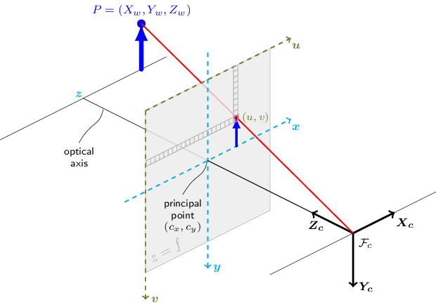
Thus, the world origin to camera0 rotation is identity matrix and translation is a zeros vector. Then R, T obtained from previous step becomes rotation and translation from world origin to camera1. Practically what this means is that your 3D triangulated points will be with respect to the coordinate systemn sitting behind your camera0 lens, as shown above.
Step5 code will do all of this and save camera0_rot_trans.dat and camera1_rot_trans.dat in camera_parameters folder. This completes stereo calibration. You get intrinsic and extrinsic parameters for both cameras. If you want to see how to use these to obtain 3D triangulation, please check my other repositories (i.e bodypose3d).
As final step, Step5 shows coordinate axes shifted 60cm forward in both camera views. Since I know that the axes are shifted 60cm forward, I can check it using a tape set to 60cm. You can see that both cameras are in good alignment. This is however not a good way to check your calibration. You should try to aim for RMSE < 0.5.

If you do not see image like this, then something has gone wrong. If you see it in camera0 and not camera1, then change _zshift to some value that you know both cameras can see.
Optional
If you must define a different world space origin from camera0, you can uncomment the code in OPTIONAL section. In this example, I define a world space origin using one of the calibration pair frames. This defines a world space origin as shown below. Note that the Z axis points into the checkerboard.

You can also replace R_W0 and T_W0 to any rotation and translation for camera0, calculated some other way. This step is easier than you think.
Finally, two additional extrinsic files will be created, with respect to a world origin:
world_to_camera0_rot_trans.dat and world_to_camera1_rot_trans.dat. These paired with the intrinsic parameters can also be used for triangulation. In this case, the 3D triangulated points will be with respect to the coordinate space defined by the calibration pattern.